Varelen Solution:
We provide full documentation packages, including IR/PI reports, turns ratio records, tap-changer verification, and acceptance forms.
Engineer Sunzhao
In the on-site commissioning work of power systems, the commissioning of oil-immersed transformers is a crucial step that must achieve "zero error". Engineering experience tells us that the electrical and mechanical stresses that a transformer bears at the moment of closing are much higher than those in its normal operating state. Therefore, any potential hazards that have not been eliminated may be magnified instantly, leading to winding displacement, bushing breakdown, light gas alarm, and even thermal faults and power outages. For users, safe and stable operation not only determines the lifespan of the equipment, but also concerns the quality of project delivery and the long-term reliability of the system.
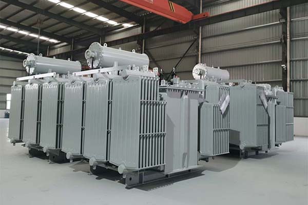
Varelen has accumulated extensive on-site experience in oil-immersed distribution and power transformer manufacturing. The pre-commissioning inspection plan we have summarized is not only applicable to new equipment but also to transformers that have been out of service for a long time and are put back into operation. From an engineer's perspective, this article systematically sorts out the key precautions before the commissioning of oil-immersed transformers and provides a set of practical guidance that can be directly applied on-site.
3. Inspection of protective components and accessory devices
Before the transformer is put into operation, it must be confirmed that all protective devices operate reliably. Especially the gas relay (Buchholz) unique to oil-immersed transformers is of vital importance for the timely diagnosis of internal faults.
Gas relay inspection
Open the exhaust valve and make sure there is no air accumulation inside.
Manually trigger the light gas and heavy gas float balls to check if the alarm and trip circuits are normal.
Check the installation Angle to ensure that the relay is within the range of 3 to 5 degrees of inclination.
Check whether the relay cavity is blocked by impurities.
Other protective devices
• Thermostat, fan starting circuit (for equipment with ONAF cooling method)
• Pressure relief valve function test
Whether the signal output of the oil level gauge is correct
• Secondary terminal wiring and protection setting value verification
These devices not only ensure the stable operation of the equipment, but also determine whether faults can be quickly isolated.
4. Insulation resistance, polarization index and transformation ratio test
Insulation testing is a core step before commissioning. Any abnormal values must be thoroughly investigated for their causes.
Insulation resistance test (IR test)
Use a 2500V or 5000V megohmmeter to test the insulation of the windings to ground and between the windings.
The data should be stable and not decline.
The difference from the factory value should not be too large (after temperature correction).
Polarization index (PI)
PI = Insulation resistance at 10 minutes/insulation resistance at 1 minute
It can be put into operation when PI ≥ 1.3
A PI of ≥ 2.0 indicates excellent insulation
Ratio test
Test whether the voltage ratios of phases A/B/C are consistent
Check whether the directional signs are correct
If the transformation ratio deviation is ≥ ±0.5%, the operation must be stopped and the cause identified
5. Confirm the matching of the tap changer position with the voltage
The tap changer (no-load or on-load) determines whether the design voltage of the transformer is consistent with the on-site system.
Inspection of no-load tap changer
Confirm that the tap position is consistent with the drawing.
Manually rotate the gear and check if the clamping position is in place.
Make sure the gear position indication is correct and not loose.
On-load voltage regulating switch (OLTC)
Check the oil level and color in the contact oil chamber
• Check the tightness of the mechanical transmission chain
Check whether the contact switching mechanism operates smoothly
Whether the OLTC filtration oil cycle meets the operational standards
Any incorrect gear position may cause the short-circuit current to exceed the limit during the initial closing