Vector Group Symbol Example: Dyn1
To illustrate, let’s break down a transformer labeled Dyn1:
- D - Delta configuration for the high-voltage winding.
- y - Star configuration for the low-voltage winding.
- n - Neutral is taken from the star side.
- 1 - 30° lagging phase displacement between HV and LV.
This vector group indicates that the transformer has a delta-connected primary winding, a star-connected secondary winding with a neutral, and a phase displacement where the LV winding lags the HV winding by 30°. This configuration is common in applications where a stable neutral point is required, and slight phase shifts are manageable.
| Phase shift(deg) |
Connection |
| 0 |
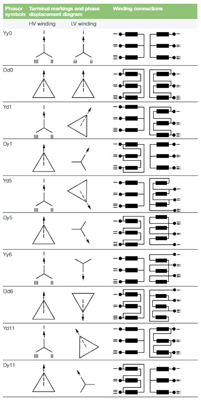
Yy0 |
Dd0 |
Dz0 |
| 30 lag |
Yd1 |
Dy1 |
Yz1 |
| 60 lag |
|
Dd2 |
Dz2 |
| 120 lag |
|
Dd4 |
Dz4 |
| 150 lag |
Yd5 |
Dy5 |
Yz5 |
| 180 lag |
Yd6 |
Dy6 |
Yz6 |
| 150 lead |
Yd7 |
Dy7 |
Yz7 |
| 120 lead |
|
Dd8 |
Dz8 |
| 60 lead |
|
Dd10 |
Dz10 |
| 30 lead |
Yd11 |
Dy11 |
Yz11 |
Additional Considerations in Vector Group Selection
Transformers may feature advanced vector groups to accommodate complex distribution needs, such as multi-winding configurations. This distinction ensures optimal performance across different voltage levels and phase demands.
For transformers built to the ANSI standard, vector groups may be replaced by diagrams illustrating the winding relationships and phases. Although similar in function, these diagrams may require different interpretation methods.
Conclusion
Transformer vector groups provide critical information on the phase displacement and winding configuration of a transformer. Properly utilizing vector groups helps prevent issues like circulating currents, which can lead to overheating or equipment failure, ensuring safe and optimal transformer operation across various industries.