One of the most common questions when selecting a medium voltage transformer is whether to choose a disc wound or a layer wound option.
Dry type Distribution Transformer windings are the conductive elements responsible for transferring energy between different voltage levels through electromagnetic induction.
Disc wound and layer wound configurations are the two primary approaches to winding construction in medium voltage dry-type transformers. Each method affects how the transformer handles stress, distributes voltage, and manages cooling.
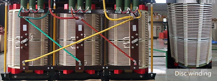
Many large power transformers are built using circular disc windings. Disk windings are usually built in a special, positive pressure regulated room, that's separate from the rest of the factory. Disc windings are made to handle the higher short circuit forces and larger impulse ratings of high voltage transformers (above 69kV). The conductors in disc wound coils form a spiral pattern, making individual discs. Once one disc is formed, a drop down (or cross-over) is used to start the formation of the second disc. For a continuously wound disc winding, the disc is wound from the inside out. Then the turns of conductor are turned over manually by hand. This allows the cross-over to the next disc to be made without splicing or braising as shown below. Special tools bend the conductor for each cross-over. This is done by hand or by automated machines.
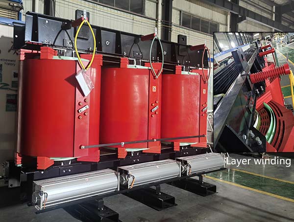
The high voltage side windings are what we call layer-wound. The conductor for the HV winding is much smaller than the large sheets used for the LV winding. Conductors for layer windings can be round or rectangular. The common choice for distribution units is enamel coated magnet wire.
The insulated magnet wire is wound around a rectangular form from top to bottom. Once at the bottom, the conductor is then wound over the first layer all the way back to the top. Some designs will use a run-back, so the start of the next turn begins again from the top of the coil. A run-back allows each layer to be wound from the top down (rather than alternate top-to-bottom and bottom-to-top). Vertical ducts are inserted between layers for cooling.
The most fundamental difference between disc and layer windings lies in the geometry and layout of the coils. This influences not only the electrical performance but also how well the unit handles mechanical forces and dissipates heat.
| Feature | Disc Wound Transformer | Layer Wound Transformer |
|---|---|---|
| Winding Configuration | Horizontal discs arranged axially | Concentric cylindrical layers |
| Preferred Voltage Range | Medium to high voltage | Low voltage (<600V) |
| Conductor Type | Strips wound flat on discs | Wires spiraling from bottom to top |
| Cooling Mechanism | Open air cooling between discs | Vertical air ducts between layers |
| Magnetic Balance | Excellent | Moderate |
| Manufacturing Cost | Lower in bulk production | Typically higher |
| Mechanical Strength | Superior axial strength | Lower axial resilience |
| Susceptibility to Disruption | Low | Higher (due to trapped air pockets) |
Disc windings form a series of horizontal discs along the axis of the transformer core. These are often split into two symmetric halves for better magnetic symmetry. Layered windings, in contrast, are arranged in concentric cylinders, often in two separate layers insulated from each other.
When transformers are exposed to sudden electrical surges, mechanical stability becomes critical. Disc wound designs generally outperform their layer wound counterparts in this respect. Their structure provides high axial mechanical strength, making them resilient under short circuit conditions.
Impulse voltage strength is crucial in medium voltage transformers due to the risk of lightning strikes, switching surges, and harmonics. Disc wound transformers have better impulse voltage distribution. Their geometry allows the voltage to spread evenly across the turns, minimizing localized stress points.
Layer wound transformers, especially at high voltage, are more prone to insulation breakdown due to uneven voltage distribution. Even when designed with enhanced insulation, they cannot match the fault tolerance of disc wound designs.
This makes disc wound transformers the preferred choice in medium and high voltage settings where transient overvoltages are common.
Although disc wound transformers may appear more complex in structure, they are often easier and more cost-effective to produce at scale. The use of strip conductors and symmetric disc layout simplifies automation in winding processes.
Layer wound transformers require more manual labor, especially in aligning and insulating each layer. The resulting cost is typically higher, especially for units with stringent quality or performance specifications.
Still, for low voltage, compact transformers where impulse strength is less critical, layered winding may be a practical and economical choice.
Reliability in transformer design is tied directly to thermal performance, dielectric integrity, and mechanical strength. Disc wound transformers score high on all three fronts:
They handle heat better due to natural airflow between discs.
Their winding geometry ensures uniform voltage stress distribution.
Their axial strength withstands short-circuit forces.
Layer wound units, while adequate in many scenarios, face challenges under high-stress conditions. The trapped air pockets and uneven thermal gradients can lead to premature insulation breakdown.
For long-term reliability in mission-critical operations, disc wound transformers offer more assurance.
Different applications demand different performance characteristics. The selection of disc or layer wound configurations must align with voltage levels, environmental factors, and the risk of transients or short circuits.
| Application | Recommended Winding | Justification |
|---|---|---|
| Data Centers | Disc | High uptime, impulse tolerance |
| Manufacturing Plants | Disc | Mechanical robustness |
| Residential Substations | Layer | Low voltage, cost-effective |
| Renewable Energy Farms | Disc | Resilient in transient conditions |
| Commercial Buildings | Layer | Budget-conscious installations |
| Mining Operations | Disc | Harsh environment, high durability |
| Hospitals | Disc | Critical power continuity |
| Small Industrial Units | Layer | Lower power requirements |
If you’re specifying a transformer for a specialized application, you must look beyond the basic voltage level. Here are additional factors to consider when choosing between disc and layer wound transformers:
Load profile: Intermittent or peaky loads benefit from disc winding due to better heat dissipation.
Installation constraints: Space-saving needs may favor layered windings in compact enclosures.
Regulatory compliance: Some standards mandate specific impulse withstand requirements.
Service environment: Corrosive or dusty atmospheres require better cooling and sealing, often favoring disc wound designs.
When working with custom transformer manufacturers like Varelen, always communicate the full operational scenario. This ensures that the transformer design meets not only technical but also regulatory and environmental expectations.
Both disc and layer wound transformers have their place in medium voltage applications, but the disc wound configuration generally offers superior performance in terms of impulse strength, mechanical durability, and thermal efficiency.
Whether you’re searching on choosing the right transformer type for your industry or you’re ready to make a purchase, Varelen Transformers can meet your needs. We offer high-quality medium voltage transformer products as well as solutions for medium voltage transformers.