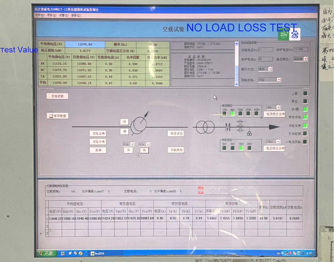
To measure losses and current at no-load. Apply rated voltage with the secondary winding open and measure losses.
Distribution Transformer power loss is divided into iron loss and copper loss, iron loss is also called no-load loss, is its fixed loss, is the loss generated by the core (also known as core loss, and copper loss is also called load loss).
Calculation formula of transformer loss
(1) Active power loss: δ P = P0+KTβ2PK
(2) Reactive power loss: δ Q = Q0+KTβ2QK
(3) Comprehensive power loss: δ PZ = δ P+KQ δ Q
Q0≈I0%SN,QK≈UK%SN
Q0 -- No-load reactive power loss (KVAR)
P0 -- No-load loss (kW)
PK -- Rated load loss (kW)
SN -- Transformer rated capacity (kVA)
I0 % -- the percentage of transformer no-load current.
UK % -- percentage of short-circuit voltage
β -- Average load factor
KT -- load fluctuation loss coefficient
QK -- Rated load magnetic leakage power (KVAR)
KQ -- Economic equivalent of reactive power (kW/kvar)
During the calculation of the above formula, the selection conditions of each parameter are as follows :(1) KT = 1.05
(2) When the minimum load is taken from the 6kV ~ 10kV step-down transformer of urban power grid and industrial enterprise power grid, its reactive power equivalent KQ = 0.1kW/kvar;
(3) transformer average load coefficient, for agricultural transformer can be β = 20%; For industrial enterprises, the implementation of three shifts, desirable β = 75%;
(4) transformer operating hours T = 8760h, maximum load loss hours: T = 5500h;
(5) transformer no-load loss P0, rated load loss PK, I0%, UK %
2, the characteristics of transformer loss
P0 -- no-load loss, mainly iron loss, including hysteresis loss and eddy current loss;
Hysteresis loss is proportional to frequency; Is proportional to the second power of the hysteresis coefficient of the maximum flux density.
The eddy current loss is proportional to the product of frequency, maximum flux density and thickness of silicon steel sheet.
PC - load loss, mainly load current through the winding in the resistance of the loss, generally known as copper loss. Its size varies with the load current and is proportional to the square of the load current; (expressed by standard coil temperature conversion values).
The load loss is also affected by the temperature of the transformer, and the flux leakage caused by the load current will produce eddy current losses in the winding and stray losses in the metal part outside the winding.
Total loss of transformer δ P=P0+PC Transformer loss ratio =PC/P0
Transformer efficiency =PZ/ (PZ+ δ P), expressed as a percentage; PZ is the output power of the secondary side of the transformer.
3. Calculation of variable loss of electric quantity
The electric quantity loss of transformer consists of iron loss and copper loss. Iron loss is related to running time, copper loss is related to load size. Therefore, the loss of electricity should be calculated separately.
1, the calculation of iron loss power: different types and capacity of iron loss power, the calculation formula is: iron loss power (KWH) = no-load loss (kW) × power supply time (hours)
2, copper loss of electricity calculation: when the load rate is 40% or below, according to the whole monthly electricity consumption (to the meter reading) 2%, calculation formula: copper loss of electricity (KWH) = monthly electricity consumption (KWH) ×2%
4, no load loss, load loss, impedance voltage calculation
No-load loss: when the secondary winding of the transformer is open and the rated voltage of the rated frequency sinusoidal waveform is applied to the primary winding, the active power consumed is called no-load loss. The algorithm is as follows: no-load loss = no-load loss process coefficient × unit loss × core.
Load loss: when the secondary winding of the transformer is short-circuited (steady state), the active power consumed by the rated current of the primary winding is called the load loss.
The algorithm is as follows: load loss = the resistance loss of the largest pair of windings + additional loss
Additional loss = winding eddy current loss + circulation loss of parallel winding wire + stray loss + lead loss
Impedance voltage: when the transformer secondary winding short circuit (steady state), the primary winding flow rated current and the voltage applied called impedance voltage Uz. Usually Uz is expressed as a percentage of the rated voltage, i.e. Uz =(Uz/U1n)*100%
Turns potential: u=4.44* F *B*At,V